
CNC Router — Owner's Manual
Safety, installation, Mach3 configuration, tooling, speeds and feeds, maintenance, and troubleshooting for the CNC routers supplied by SWYFT Robotics. The CO2 laser cutters have a separate manual.
Safety
Read before operating. The cutter is exposed, turns at up to 24,000 rpm, and will draw in anything it contacts. There is no interlock between the operator and the tool. Every safeguard on these machines is procedural.
Entanglement hazard. Do not wear gloves
A rotating cutter catches gloves, sleeves, and hair and pulls the operator into the tool faster than they can react. This causes severe injury or amputation. Do not wear gloves, loose sleeves, drawstrings, lanyards, or jewelry near the machine. Tie back long hair.
1.1Safeguards
The laser provides its own safeguards through the enclosure and interlock. These machines do not. The operator establishes them before each job.
- Tool held in a clean, correctly sized collet
- Stock clamped against cutting force
- Program air-cut before it touches material
- Eye protection on everyone in the area
- Operator at the emergency stop for the full run
All five are required. Do not start a job with any of them missing.
1.2Operating rules
Eye protection for everyone in the area
Milling ejects chips at speed. Aluminum chips are hot and sharp. Safety glasses are required for everyone in the room, not only the operator. Use hearing protection for extended runs.
Do not reach into the work area while the spindle can turn
The spindle coasts for several seconds after being commanded to stop. Wait until it has stopped completely before reaching in, including to clear a chip or check a part.
Know the emergency stop
Locate and test it before first use. The operator must be able to reach it without moving from position.
Do not leave a running job
Tools break, clamps shift, and stock moves. Stay with the machine for the full cut.
Clear chips with a brush or vacuum
Never clear chips by hand. Stop the spindle first.
Student operation
New operators must observe a full job, then run one start to finish under supervision, before working alone. Cover the glove and clothing rule explicitly.
1.3Materials
Aluminum, Delrin, polycarbonate, wood, and composites are all normal work on these machines. Polycarbonate machines cleanly here and should not be cut on the laser.
Composite dust and magnesium
Carbon fiber and fiberglass produce fine abrasive dust that causes respiratory injury and damages bearings and rails. Use extraction at the cutter and respiratory protection, and clean the machine afterward. Do not machine magnesium. Magnesium chips ignite, and water intensifies the fire.
1.4Before every job
- No gloves, loose sleeves, jewelry, or untied hair
- Eye protection on everyone in the area
- Tool seated in a clean, correctly sized collet
- Stock clamped, clamps clear of the toolpath
- Spindle coolant circulating
- Program air-cut
- Emergency stop reachable
Reference
Both routers share one architecture: a benchtop machine with a water-cooled spindle on ball screws, controlled from Mach3 on Windows over USB. What this manual says applies to both; where they differ — collet size, spindle range, work area — the difference is called out.
2.1Specifications
| Specification | 8060Z | OMIO X8-2200L-USB |
|---|---|---|
| Work area | 575 × 375 mm or 790 × 580 mm by variant | 770 × 565 mm; Z 85 mm (140 mm with the dust cover removed) |
| Spindle | 1.5 kW or 2.2 kW by variant, water-cooled | 2.2 kW, water-cooled |
| Spindle speed | 3,000–24,000 rpm | 6,000–24,000 rpm |
| Tool holding | ER16 1/8″ collet with 1.5 kW spindle; ER20 1/8″ collet with 2.2 kW spindle | ER20 collet — 6 mm fitted, 3.175 mm included |
| Motion | C7 ball screws (X/Z 1605, Y 2005) on chrome shafts and linear bearings | Ball screws (X/Z 1605, Y 2005) on HG20 linear rails |
| Frame | 6061-T5 extruded aluminum | 6061-T5 extruded aluminum |
| Max feed | — | 4,000 mm/min |
| Positioning accuracy | — | 0.05 mm |
| Included extras | Limit switches, tool-length probe, four clamps, water pump; optional 4th axis (110 mm swing) | Limit switches, wireless pendant on some builds |
| Control software | Mach3 (Windows), USB | Mach3 (Windows), USB |
| Power supply | 110 V | 110 V |
| Weight | — | 90 kg |
Figures are from each machine's published specification; a dash means that number is not published. The documentation shipped with the machine is the authority on the hardware.
2.2Required support systems
| System | Requirement |
|---|---|
| Spindle cooling | Closed water loop circulating before the spindle turns |
| Chip management | Dust shoe and vacuum for wood and plastic. Air blast or mist for aluminum |
Running the spindle without coolant destroys the bearings within minutes.
2.3Machine anatomy
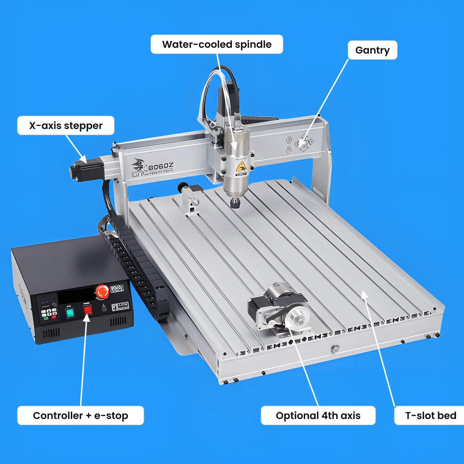
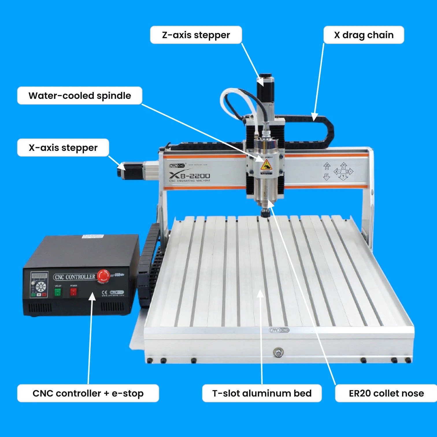
Both machines put the same parts in the same places: the spindle rides the gantry (the X axis), the gantry rides the bed (Y), and the controller box carries the e-stop, spindle VFD, and USB link. The visible differences are scale and the collet at the spindle nose — ER16 (1.5 kW) or ER20 (2.2 kW) on the 8060Z, ER20 on the X8.
Installation
Disconnect power before installation
An unintended spindle start with hands in the work area causes severe injury. Disconnect power before installation, adjustment, or maintenance. These machines are heavy and awkward to lift; use enough people.
3.1Unpacking and mounting
Inspect for transit damage
Check the gantry, spindle, and ball screws. Turn the spindle by hand to confirm it moves freely. Photograph any damage and email support@swyftrobotics.com before powering on.
Mount on a rigid bench
The bench must carry the weight without flexing. Bench flex appears as chatter in the finish and shortens tool life. Level the machine and bolt it down where possible.
Set up spindle cooling
Fill the reservoir, connect the lines, and run the pump. Confirm water circulates and returns warm after one minute of spindle running.
Connect the controller
Wire the controller to the machine and to mains as shown in the machine's documentation, then connect tothe PC over USB. Confirm the controller and pendant power on before jogging.
3.2Software and configuration
Install Mach3 and the USB motion-controller driver, then load the supplied XML profile. It contains the axis directions, steps-per-unit, soft limits, and spindle configuration for the machine. Do not enter these values manually. The X8's package is linked below; the 8060Z ships with its profile and drivers on the U-disk in the box — email support@swyftrobotics.com for a replacement copy.
Configuration changed in August 2024
Loading the wrong package produces axes that move the wrong distance or direction. Confirm the machine's ship date before loading a profile. Contact support with the serial or order number if unsure.
3.3First movements
Jog each axis
With no tool fitted, jog X, Y, and Z a short distance. Confirm each moves the commanded direction and distance. Incorrect direction or distance means the wrong profile is loaded. Correct it before continuing.
Verify soft limits
Move slowly toward each end of travel and confirm the machine stops where expected.
Run the spindle unloaded
With no tool fitted and coolant running, start the spindle at low speed. Confirm smooth running and free coast-down.
Tooling and workholding
A tool that is not held correctly, or stock that is not clamped, becomes a projectile. Both are the most common causes of injury and scrapped parts on these machines.
4.1Collets and tool fitting
Match the collet to the shank
On the 8060Z, the 1.5 kW spindle takes ER16 collets and the 2.2 kW spindle takes ER20. The X8 takes ER20. Collet sizes are not interchangeable, and each grips only within a narrow range of its nominal size. A 6 mm collet does not hold a 1/4 in (6.35 mm) shank. A mismatched collet allows the tool to pull out during the cut.
Seat the collet in the nut first
Insert the collet into the nut at an angle and snap it into the retaining ring before threading the nut onto the spindle. A tool must not be in the collet at this stage.
Never tighten an empty collet
Tightening without a tool fitted deforms the collet.
Engage sufficient shank, then tighten
Insert the shank so it is gripped along its length, keeping the flutes clear of the nut. Tighten firmly with both wrenches.
Keep the collet and taper clean
Debris in the taper prevents the collet seating true. The result is runout: oversize cuts, poor finish, and rapid tool wear. Wipe both at every tool change.
The 1.5 kW spindle comes with an ER16 1/8″ collet. The 2.2 kW spindle comes with an ER20 1/8″ collet. We recommend this ER20 collet set (alternate) for ER20 collets and this ER16 collet set for ER16 collets.
4.2Workholding
| Stock | Method |
|---|---|
| Plate and thick stock | Step clamps, low-profile clamps, or a fixture plate in the T-slot bed |
| Thin sheet | Sacrificial spoilboard with tabs in the toolpath, double-sided tape, or tape and adhesive |
| All stock | Verify every clamp is clear of the toolpath and the gantry before starting |
Low-profile clamps reduce the risk of gantry collision. Clamp against the direction of cutting force.
Never hold work by hand
Hand-held work is pulled into the cutter. Clamp all stock, including small parts and short cuts.
Speeds and feeds
Starting values for a sharp 2-flute carbide end mill in a rigid setup.
These values are a starting point, not a specification
Correct values depend on tool diameter, flute count, depth of cut, and setup rigidity. The tool manufacturer's data for the specific cutter takes precedence. Start conservative and increase.
5.1Starting values
| Material | Tool | RPM | Feed (mm/min) | Depth per pass |
|---|---|---|---|---|
| Aluminum 6061 | 1/4" (6 mm) 2-flute | 16,000–18,000 | 800–1,400 | 0.3–0.8 mm |
| Aluminum 7075 | 1/4" (6 mm) 2-flute | 16,000–18,000 | 700–1,200 | 0.3–0.6 mm |
| Delrin / acetal | 1/4" (6 mm) 2-flute | 14,000–18,000 | 1,200–2,000 | 1–3 mm |
| Polycarbonate | 1/4" (6 mm) 1- or 2-flute | 12,000–16,000 | 1,000–1,800 | 1–2 mm |
| Hardwood | 1/4" (6 mm) 2-flute | 16,000–20,000 | 1,500–2,500 | 2–4 mm |
| Plywood / MDF | 1/4" (6 mm) 2-flute | 16,000–20,000 | 1,500–2,500 | 2–5 mm |
| SWYFT Composite (SRPP) | 1/4" (6 mm) 2-flute | 14,000–18,000 | 1,000–1,800 | 1–3 mm |
These values correspond to 0.025–0.06 mm of material per tooth. Scale for other tools with: feed = rpm × flutes × chip load. A 3 mm cutter requires proportionally less feed and shallower passes. Below roughly 0.02 mm per tooth the cutter rubs instead of cutting, generating heat and dulling the edge. Aluminum requires chip clearing with air or mist. Plastics require fewer flutes and higher feed to carry heat away in the chip.
5.2Assessing the cut
| Observation | Meaning | Action |
|---|---|---|
| Uneven, rattling tone | Chatter from flex | Reduce depth per pass, increase feed, shorten tool, improve workholding |
| Dust instead of chips | Tool rubbing | Increase feed or reduce rpm |
| Gummy strings re-welding into the cut | Heat not carried away | Increase feed, reduce rpm, use fewer flutes |
| Tool or part too hot to touch | Chips not clearing heat | Increase feed, reduce rpm, reduce depth, improve chip clearing |
When uncertain, reduce depth per pass and maintain feed.
Operation
6.1CAM and posting
Program toolpaths in Fusion 360 or another CAM package and post with a Mach3-compatible post-processor. Simulate the full program before posting. Verify the tool number, spindle speed, and units in the posted G-code header.
6.2Zeroing and air cut
Set the work coordinate system
Set X and Y origin to the datum used in CAM. Set Z-zero to the top of the stock or the spoilboard, matching the program. An incorrect Z-zero drives the cutter into the bed.
Air-cut the program
Raise Z clear of the work and run the full program. This detects an incorrect zero, a clamp in the toolpath, an unexpected rapid, or a missed tool change without risk to the machine or stock.
Cut a test in scrap
Run the toolpath in offcut material at reduced feed before cutting the final stock.
Monitor the first pass
Remain at the machine with access to the emergency stop for the full run.
Maintenance
Disconnect power before maintenance
Perform all maintenance with the machine powered down.
7.1Service schedule
| Interval | Clean | Check |
|---|---|---|
| After every job | Chips from bed, rails, and ball screws | Tool condition · collet and taper |
| Weekly | Whole machine, including under the gantry | Coolant level · hose connections · clamp hardware |
| Monthly | Rails and ball screws, then lubricate | Rail lubrication · spindle runout · coupling condition |
| Every 3–6 months | Coolant loop | Full coolant change · fasteners re-torqued |
Chips left on the rails are drawn into the linear bearings and are the primary cause of premature wear. Vacuum after every job.
7.2Procedures
Clear chips
Vacuum the bed, rails, and ball screws with the machine powered down. Aluminum chips are abrasive and migrate into the bearings.
Lubricate rails and ball screws
Wipe the linear rails or shafts and the ball screws clean, then apply the lubricant specified in the machine's documentation. Remove excess; surplus grease collects chips.
Check spindle runout
With a clean collet and a known-good tool, check for movement at the tip. Increasing runout indicates a damaged collet, a contaminated taper, or worn spindle bearings.
Change spindle coolant
Drain, flush, and refill the loop. Algae in old coolant restricts flow and overheats the spindle.
Re-torque fasteners
Check gantry, spindle mount, and bed fasteners. A loose spindle mount presents as chatter.
Troubleshooting
8.1Fault table
| Symptom | Possible cause | Action |
|---|---|---|
| Axis moves the wrong direction or distance | Incorrect Mach3 profile | Load the XML profile for the machine's build date. See Section 3.2 |
| No connection to Mach3 | USB driver, cable, or port | Reinstall the USB motion driver. Try another port and cable. Confirm controller power |
| Chatter or rough finish | Depth too great; feed too low; long tool; flexing stock or bench | Reduce depth, increase feed, check workholding and bench rigidity |
| Tool pulls out during the cut | Wrong collet size; insufficient shank engaged; nut under-tightened; contaminated taper | Stop immediately. Match collet to shank, clean both, engage more shank, tighten fully |
| Repeated tool breakage | Feed too high for diameter; depth too great; chips re-cutting; dull tool | Reduce depth per pass, improve chip clearing, replace the tool |
| Aluminum welding to the cutter | No chip clearing; rpm too high for feed | Add air blast or mist. Increase feed, reduce rpm |
| Spindle overheating or alarming | Coolant not circulating; low level; blocked line | Stop the spindle. Confirm pump operation and flow before restarting |
| Cut in the wrong position | Work coordinate system or Z-zero | Re-zero and air-cut before running again |
Support
Anything in this manual unclear, or a step not matching your machine? Email support@swyftrobotics.com with your machine model and we'll walk you through it.
Email support