
CO2 Laser Cutter — Owner's Manual
Safety, installation, parameters, maintenance, and troubleshooting for the CO2 laser cutters supplied by SWYFT Robotics. The OMIO X8 CNC router has a separate manual.
Safety
Read before operating. Everyone who runs the machine must read this section, including students working under supervision.
Coolant and fume extraction are required
Running the laser without circulating coolant or active fume extraction will crack the laser tube and expose operators to harmful smoke. Confirm both are running before every job.
1.1Safeguards
Safe operation depends on independent safeguards, not on operator attention. Three protect routine cutting: the lid interlock prevents the laser firing while the enclosure is open, the job starts only on operator command, and the beam stays inside a closed cabinet. All three must fail before anyone is exposed.
Do not defeat any of them. Never bypass the lid interlock, never run with a panel removed, and never operate the machine with the enclosure open.
1.2Operating rules
Keep the enclosure closed
CO2 laser light is infrared and invisible. Keep the lid closed for every job. Never bypass the lid interlock.
Do not leave a running job
The beam cuts by burning. Stay with the machine for the full cut. Keep a CO2 or Class ABC extinguisher within reach and clear scrap from the bed between jobs.
Know the emergency stop
The emergency stop cuts laser power immediately. Locate and test it before first use. On flame, smoke, unusual odor, or any electrical fault: press the emergency stop, then disconnect main power.
Electrical
Connect to a grounded outlet that matches the nameplate: 110 V / 60 Hz 1-ph (US) or 220 V / 50–60 Hz 1-ph (export). Give the machine its own dedicated grounded circuit. Do not use extension cords or power strips; a surge protector must be rated over 2,000 J. The cabinet contains high-voltage components. Do not open it. While the laser key is on, touch the machine with one hand at a time — a habit that keeps any accidental shock from crossing the chest. Contact SWYFT Robotics support before any electrical service.
Fire response
Cut power — emergency stop, then main power — before using the extinguisher. Discharging too close to the flame can scatter burning debris; know your extinguisher's working range. Post the local fire department's number where the machine is used.
Pass-through doors
The pass-through doors let long stock feed through the enclosure, and open a path for scattered beam energy. When either door is open: only material passes through the opening, everyone nearby wears laser safety glasses rated OD 5+ at 10.6 µm, and extraction must still capture the fumes. Close both doors when not in use.
Student operation
Students operate only with a trained adult supervising, every session — supervision is not a training phase that ends. New operators complete a supervised start-to-finish job before running the machine, and review the emergency stop, extinguisher location, and ventilation at the start of every build season.
1.3Prohibited materials
Toxic gas and fire hazard
Processing prohibited materials releases toxic gas and can start a fire. Exposure causes respiratory injury, and the residue corrodes the machine. Never process the materials listed below. If a material cannot be identified, do not process it.
| Material | Reason |
|---|---|
| PVC, vinyl, PVB | Releases chlorine compounds that form hydrochloric acid in lungs and machine |
| PTFE (Teflon) and other fluoropolymers | Releases fluorine compounds; highly toxic |
| Polycarbonate (Lexan) | Toxic fumes, and it melts and discolors instead of cutting. Use the CNC router |
| Chrome-tanned or synthetic leather | Releases toxic fumes (chromium VI) unless certified laser-safe |
| Any metal | Cannot be cut by a CO2 laser. Bare-metal marking requires a dedicated coating; the beam reflects off the metal itself |
| ABS — SWYFT shop policy | Releases hydrogen cyanide when burned; melts into the cut |
| Phenolic and epoxy resins, including most FR4/garolite — SWYFT shop policy | Toxic fumes |
| Fiberglass, carbon fiber — SWYFT shop policy | Toxic, abrasive dust; conductive carbon dust also shorts electronics |
| HDPE, thin plastic film — SWYFT shop policy | Melts and ignites |
The first five rows are the machine maker's own prohibitions. The rows marked SWYFT shop policy go further: some makers list ABS and HDPE as machine-compatible, but their fume and fire behavior has no place in a student shop, so we prohibit them too. Confirm any unlisted material against its Safety Data Sheet before processing.
1.4Before every job
- Fume extraction running
- Coolant circulating and at temperature
- Material confirmed laser-safe
- Fire extinguisher within reach
- Bed clear of scrap
- Lid closed, interlock functional
Reference
SWYFT Robotics supplies three CO2 laser cutters. All use a sealed water-cooled glass tube at 10.6 µm, run on a factory-set 110 V or 220 V single-phase supply (match the nameplate; never 380 V 3-ph), and are driven from LightBurn. Controller and bundled software differ by model. Identify your model before following Sections 3 and 5.
2.1Specifications
| Specification | Compact 100 W | 100 W | 130 W |
|---|---|---|---|
| Rated tube power | 100 W | 100 W | 130 W |
| Work area | 27.6" × 19.6" | 39.4" × 31.5" | 55.1" × 35.4" |
| Work area (mm) | 700 × 500 | 1000 × 800 | 1400 × 900 |
| Bundled software | AutoLaser | AutoLaser | RDWorks 8 (Ruida RD6445) |
| Machine size (mm) | 1160 × 875 × 600 | 1460 × 1175 × 630 | 1860 × 1320 × 940 |
| Weight | 93 kg | 140 kg | 400 kg |
| Power supply | 110 V ±10% / 60 Hz 1-ph or 220 V ±10% / 50–60 Hz 1-ph (factory-set; see nameplate) | 110 V ±10% / 60 Hz 1-ph or 220 V ±10% / 50–60 Hz 1-ph (factory-set; see nameplate) | 110 V ±10% / 60 Hz 1-ph or 220 V ±10% / 50–60 Hz 1-ph (factory-set; see nameplate) |
| Max engraving speed | 800 mm/s | 800 mm/s | 800 mm/s |
| Max cut depth | 0–10 mm | 0–10 mm | 0–10 mm |
| Ambient operating temp | 5–35 °C | 5–35 °C | 5–35 °C |
| Ambient humidity | 70% max | 70% max | 70% max |
| Laser wavelength | 10.6 µm (10,600 nm) | 10.6 µm | 10.6 µm |
Figures are from each machine's published specification. Two models are 100 W and differ only in bed size; they share the parameters in Section 6. Voltage is factory-set: US stock is 110 V ±10%, 60 Hz, 1-ph; export and custom orders are 220 V ±10%, 50/60 Hz, 1-ph. Match the nameplate. These machines are never 380 V 3-ph. Ambient temperature is the room, not the coolant — best results below 25 °C. Maximum cut depth varies with material and settings. The full hardware documentation ships on the included USB drive.
All three models include one-button autofocus, a red-dot pointer, front and rear pass-through doors, honeycomb and aluminum blade beds, an electric bed lift, a lid interlock, coolant flow protection, and an emergency stop.
Duty cycle and tube life
Stop for at least 30 minutes after 3.5 hours of continuous cutting. Power setting drives tube lifespan: expect roughly 12,000 hours kept under 40% power, 10,000 hours at 40–70%, and 8,000 hours above 70%. The tube does not fire below 10% power; treat 70% as the working ceiling and reach for slower speed or extra passes instead of more power.
2.2Required support systems
| System | Requirement |
|---|---|
| Water cooling | At least 7.5 L (2 gal) of distilled water circulating through the tube, held at 15–21 °C. Hard limits: never below 10 °C or above 38 °C |
| Fume extraction | Ducted outdoors, or to a carbon filter rated for laser fumes |
| Air assist | Air delivered at the nozzle throughout the cut |
All three must be running before the laser fires. Loss of any one damages the machine, the work, or the operator.
2.3Machine anatomy
Every control and access point referenced in this manual is labeled below on the 130 W flagship. The two 100 W models and the Compact share the same layout at smaller scale — lid, bed, gantry, and electronics bay are in the same relative positions on all four machines.
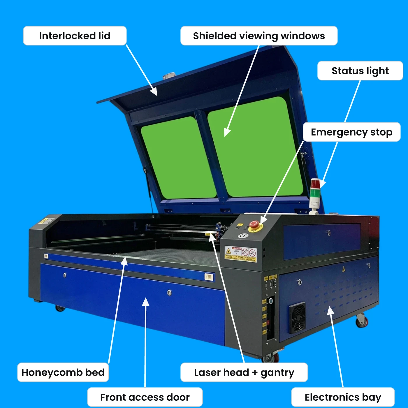
The tube at the rear generates the beam; three mirrors relay it to the head, where the lens focuses it onto the material. Understanding this path explains most of this manual's maintenance: two of the three mirrors move with every job, so alignment (chapter 4) and mirror cleaning (chapter 7) are what keep cutting power at the material.
Installation
Disconnect power before installation
Performing installation or adjustment with the machine connected to power can cause electric shock. Disconnect power first. The machine is heavy and the glass tube is fragile. Use enough people for the lift, and cut shipping banding with care, as it springs when released.
3.1Unpacking and positioning
Remove all shipping restraints
Foam blocks and zip ties secure the gantry and head in transit. Remove every one before jogging the machine. Retain the packaging for future transport.
Inspect for transit damage
Check the tube, mirrors, and lens. Photograph any damage and email support@swyftrobotics.com before powering on.
Position the machine
The 130 W is a floor machine at 1860 × 1320 × 940 mm and 400 kg. The two 100 W models are 600–630 mm tall; the Compact is 93 kg and requires a rigid stand or bench rated for its weight. All models ship by freight on a pallet.
Allow clearance
Leave generous space on every side for airflow, access, and the exhaust run. Position near the vent exit and a grounded outlet. Keep a separate work table nearby so nothing is ever staged on top of the machine.
Control the room
The room must hold 5–35 °C and stay under 70% humidity, clear of the dew point — condensation on cold optics and electronics is a fault waiting to happen. Keep the machine out of direct sunlight and away from dust, strong electromagnetic sources, and anything flammable or corrosive stored nearby.
3.2Water cooling
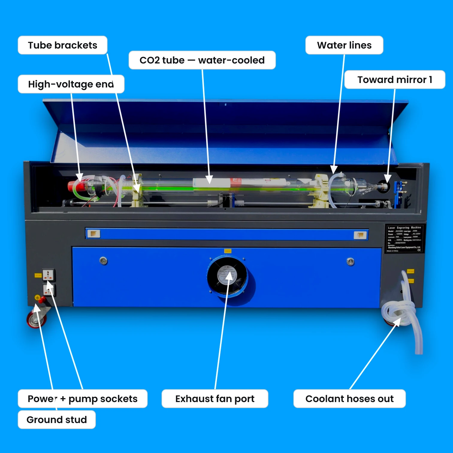
Connect the coolant lines
The pump outlet feeds the tube inlet. The tube outlet returns to the pump inlet. Flow travels in the same direction as the beam, toward mirror 1. Secure every connection with a clamp.
Fill with distilled water only
At least 7.5 L (2 gal), enough to keep the pump fully submerged. Tap water scales the tube; additives and automotive antifreeze leave conductive, corrosive residue. Top up every few days — evaporation will expose the pump. Never handle the pump or reach into the tank while the pump is powered; unplug it first.
Confirm flow before firing
Run the pump and confirm water moves through the tube with no trapped air. Pinch and release the line to clear a bubble. Hold coolant at 15–21 °C; never below 10 °C or above 38 °C — cold shock and overheating both crack the glass. On hot days, floating sealed bottles of ice in the tank cools the water without diluting it. Confirm flow before every session. Do not rely on the flow sensor alone.
Using a chiller instead
An industrial water chiller replaces the pump and tank and holds temperature automatically. Connect the chiller's outlet to the machine's water inlet and its inlet to the machine's water outlet, and run it on a separate circuit where possible.
Freezing damages the tube
Water expanding as it freezes will crack the laser tube. Drain the cooling system if the machine is stored below freezing.
3.3Exhaust and air assist
Duct the exhaust blower outdoors or to a carbon filter rated for laser fumes. Keep the run short and straight. Long or kinked hose reduces airflow and leaves smoke staining on cut edges. Connect the air assist pump and confirm air is delivered at the nozzle.
3.4First power-on
Do not disassemble the optical path
The machine is assembled, aligned, and test-cut before shipping. Removing or reseating a lens or mirror can damage the component and disturb the alignment. Do not open the optical path. Report visible damage to support@swyftrobotics.com.
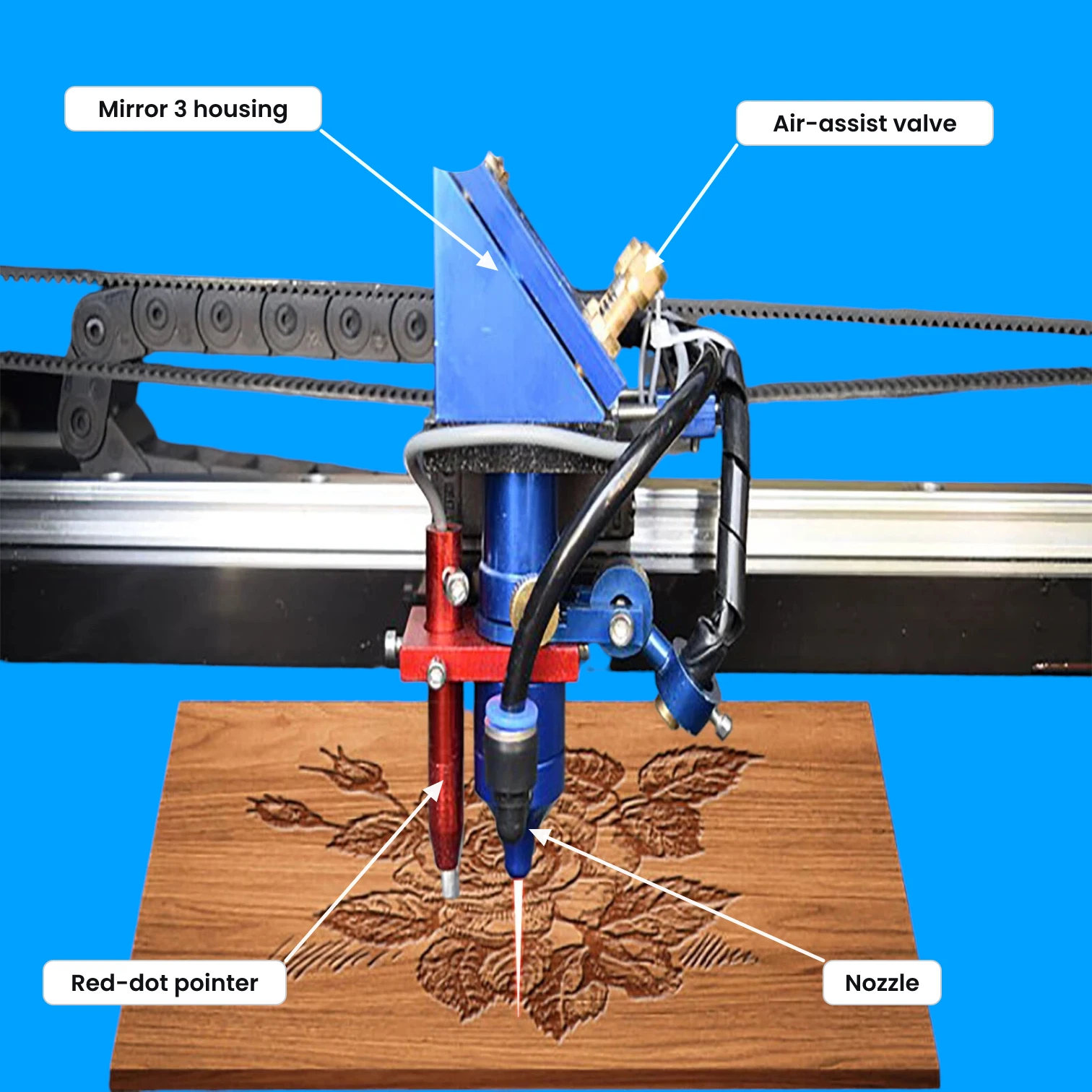
Power on and note the home corner
Release the emergency stop and switch on. Let the controller boot and home the head. The corner it homes to is the origin.
Set focus
Place material on the bed and press autofocus on the control panel. Manual alternative: rest the included acrylic focus gauge on the material and raise the bed until the nozzle just touches the gauge without pressing on it. Never focus, by either method, without material on the bed.
Position the computer
Keep a USB- or Ethernet-connected computer within about 4.5 m (15 ft) of the machine — longer runs invite signal dropouts mid-job.
Frame the job
With the lid closed, use Frame to trace the job outline with the head before cutting. This confirms material position and that the job fits the bed.
3.5Power-up and shutdown sequence
| Order | Power up | Shut down |
|---|---|---|
| 1 | Coolant pump. Confirm flow | Run exhaust 1 minute to clear the cabinet |
| 2 | Exhaust and air assist | Laser key off |
| 3 | Main power, release e-stop | Main power off |
| 4 | Laser key on. Let the head home | Coolant off after 2 minutes |
Coolant runs first and stops last. Firing without flow cracks the tube. After shutdown, pull the laser key, clear debris from the bed and tray, and switch off or unplug the machine's supply — keyed-off and unpowered is the storage state.
3.6First cut
Cut a test grid at the starting values for your material from Section 6. Adjust speed, power, and passes until edges are clean and the cut drops through. Save the working values as a LightBurn material entry. Watch the first pass of any new job.
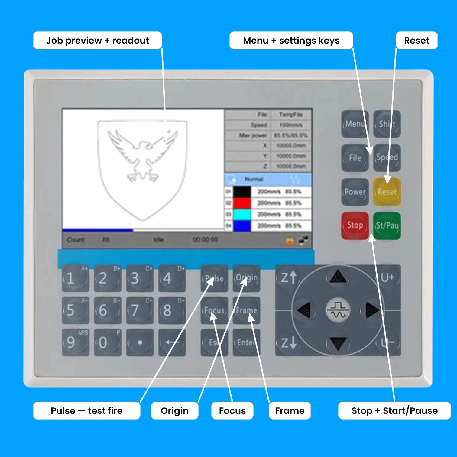
3.7Electrical grounding
The laser power supply runs at several thousand volts, and a solid earth ground is what makes a fault survivable. A properly wired three-prong grounded outlet provides this. Never lift the ground with a 3-to-2 adapter, and never run the machine ungrounded.
If no grounded outlet exists at the location, the cabinet's dedicated grounding lug must be bonded to earth before first power-on: a single rod driven at least 2.5 m (8 ft) into soil — or two rods at least 1.2 m (4 ft) each — placed at least 1.5 m (5 ft) from the machine, with no more than 5 Ω of resistance end to end. Have the connection checked periodically for corrosion and loosening. If that is not practical at your site, have an electrician install a grounded outlet instead — that is the better fix.
Dedicated circuit
Give the machine its own circuit — it needs the full amperage, and sharing the circuit trips breakers mid-cut. Supply fluctuation must stay under 5%; if the inlet fuses blow repeatedly, suspect the supply. Surge protection must be rated over 2,000 J.
3.8Commissioning checks
The machine ships with the emergency stop pressed in; release it by pulling up. Before the first real job — and after any move or service — prove both safety interlocks work. Both tests run with the cover closed and scrap material on the bed.
Test the emergency stop
With coolant running and scrap on the bed, fire a brief test pulse from the control panel, then press the emergency stop mid-pulse. The laser must cut off instantly. If it keeps firing, stop — the machine is not usable until the switch is replaced. Contact support@swyftrobotics.com.
Test the lid interlock
Start a small job on scrap, then open the cover. The beam must stop the moment the lid lifts. If it does not, stop and contact support. Never operate a machine whose interlocks fail, and never disable them.
Mirror alignment
Machines are aligned and test-cut before shipping. Normal operation does not move the mirrors. Do not align them.
Exposed laser beam
Mirror alignment requires firing the laser with the enclosure open. The beam is invisible and can cause severe burns and permanent eye injury. Do not perform mirror alignment. Contact SWYFT Robotics support at support@swyftrobotics.com.
4.1When alignment is required
Alignment is required only after a laser tube or mirror is replaced, or after visible transit damage. It is not routine maintenance and not a seasonal task. Do not adjust the mirrors to increase cutting power.
4.2Check these first
Weak or uneven cutting is usually one of the following. Each is safe to check with the machine shut down and the enclosure closed.
| Check | Action |
|---|---|
| Focus | Re-run autofocus with material on the bed |
| Optics | Clean the lens and mirrors in place. See Section 7 |
| Settings and material | Verify against Section 6. Confirm the material and its thickness |
| Air assist | Confirm air is delivered at the nozzle |
| Tube age | Output falls over tube life. Contact support |
If all checks pass and the machine still cuts unevenly across the bed, contact support@swyftrobotics.com. Do not adjust the mirrors.
4.3Service
Contact support@swyftrobotics.com. In most cases the cause can be identified by email, and alignment can be carried out on a call or arranged as a service visit. This manual does not publish an alignment procedure.
Software
5.1LightBurn
LightBurn drives all three models and is the recommended software. Download it from lightburnsoftware.com for Windows or macOS. A Ruida machine requires the tier that supports DSP controllers. Check LightBurn's site for current tiers and pricing.
Add the machine
Devices → Create Manually. Select the controller for your model. The 130 W uses a Ruida RD6445. The two 100 W models ship with AutoLaser and are not Ruida; check the controller label, or contact support. Enter the bed dimensions from Section 2.1.
Connect
Connect over USB or Ethernet. Confirm the status bar reads Ready. Save a backup of the default settings.
Import from CAD
Export as DXF and import with File → Import. Assign layers by color.
Set speed and power per layer
Set values for each color layer in the Cuts / Layers panel, starting from Section 6.
Frame, set origin, run
Set focus, frame the job, set the origin, then start. Watch the first pass.
5.2Bundled software
Each machine ships with its bundled software on the included USB drive. The 130 W includes RDWorks 8, which opens .rd files. The two 100 W models include AutoLaser. Both run offline and are useful where the machine has no network access. Supported import formats across the range include DXF, AI, SVG, BMP, and JPG. Transfer over USB, Ethernet, or USB drive.
Cut and engrave parameters
Starting values. Test on scrap before production.
These values are a starting point, not a specification
Results vary with tube age, lens condition, air pressure, alignment, focus, and material batch. No published chart is correct for every machine. Test on scrap, then save the values that work in your LightBurn material library.
Units and scaling
Speeds are mm/s. Confirm the controller is not set to inch/s. Power is a percentage of rated tube power. Columns are by tube wattage: both 100 W models use the 100 W column. Power is the same across models; speed scales with wattage. All values assume air assist on and focus set to the material surface.
6.1Cutting
| Material (thickness) | Power | 100 W | 130 W |
|---|---|---|---|
| Cast acrylic (3 mm) | 35–55% | 15–25 | 20–32 |
| Cast acrylic (6 mm) | 55–70% | 8–12 | 10–16 |
| Cast acrylic (10 mm) | 75–90% | 4–6 | 5–8 |
| Delrin / acetal — POM (3 mm) | 70–85% | 10–15 | 13–20 |
| Delrin / acetal — POM (6 mm) | 80–90% | 5–8 | 6–10 |
| Baltic birch plywood (3 mm) | 60–75% | 12–20 | 16–26 |
| Baltic birch plywood (6 mm) | 80–90% | 6–10 | 8–13 |
| MDF (3 mm) | 70–85% | 10–16 | 13–21 |
| Basswood / balsa (3 mm) | 40–55% | 20–30 | 26–39 |
| SWYFT Composite / SRPP (1.75 mm) | 50–65% | 15–25 | 20–32 |
| SWYFT Composite / SRPP (3 mm) | 55–70% | 11–18 | 14–23 |
| SWYFT Composite foam core (6 mm) | 60–75% | 8–14 | 10–18 |
| EVA foam (6 mm) | 45–60% | 15–25 | 20–32 |
| Cork (3 mm) | 45–60% | 15–25 | 20–32 |
| Veg-tan leather (2–3 mm) | 40–55% | 20–30 | 26–39 |
| Felt / natural fabric | 20–35% | 40–70 | 50–90 |
| Chipboard / corrugated card | 30–45% | 25–45 | 33–58 |
| Paper / cardstock | 15–25% | 60–100 | 78–130 |
Speeds in mm/s. Cast acrylic gives a flame-polished edge; leave the protective film on while cutting. Delrin requires more power and lower speed than acrylic at the same thickness. Plywood and MDF vary by species, glue, and batch; re-test each sheet. Do not process wood with a lacquered or varnished surface. Paper, card, cork, and felt are flammable; do not leave the machine unattended.
Do not run the tube at 100%
Sustained full power shortens tube life. If a material does not cut through at the top of its range, reduce speed or add a pass.
6.2Engraving
| Material | Power | 100 W | 130 W |
|---|---|---|---|
| Wood — birch / basswood | 15–30% | 150–300 | 195–390 |
| Cast acrylic (frosted) | 15–25% | 200–350 | 260–450 |
| Anodized aluminum (marking) | 20–35% | 200–400 | 260–500 |
| Veg-tan leather | 15–30% | 200–350 | 260–450 |
| Slate / ceramic tile | 30–45% | 120–250 | 155–325 |
| Glass (frosting) | 25–40% | 150–250 | 195–325 |
| Coated / painted metal | 25–40% | 150–300 | 195–390 |
Speeds in mm/s, within the 800 mm/s engraving limit. Engraving marks the surface and does not cut through. For photographic detail, reduce line interval and power rather than speed. Anodized aluminum and coated metal are marked, not cut. Cover glass with wet paper or dish soap.
| Material family | Technique |
|---|---|
| Glass, ceramic, stone | Brittle materials crack from concentrated heat. Run extra passes at lower settings instead of one hot pass, and expect dust — ceramics and stone call for respiratory protection in repeated work |
| Plastics (acrylic, POM, PETG) | Melt before they burn. Favor low power at high speed, and drop engraving resolution to medium or low — dense lines concentrate heat and melt detail |
| Coated metal | Only the coating marks; the metal beneath reflects the beam. Coatings on aluminum generally want faster, lower-power passes than the same coating on steel. Follow the coating maker's numbers |
| Paper, card, leather | Narrow window between too light and burned through — test each batch, watch for flame, and never step away |
| Wood engraving | Start low and rerun the job for more depth. Depth beyond what the design needs only chars the floor of the engraving |
A default of 500 DPI suits most engraving; plastics usually improve at lower resolution. When in doubt, start weak and fast, then repeat the job stepping power up — a light result can always be run again; a burned one cannot be undone.
6.3Adjusting
Use a material test grid
LightBurn's Material Test generator sweeps speed against power on one tile. Run it on scrap and read the values off the axes.
| Symptom | Cause | Action |
|---|---|---|
| Cut does not go through | Speed too high | Reduce speed in small steps. Add a pass rather than raising power to maximum |
| Charred or flaming edges | Power too high, or speed too low | Increase speed or reduce power. Confirm air assist |
| Melted or fused edges | Material melting instead of vaporizing | Increase speed, reduce power, confirm focus at the material surface |
| Clean at one corner, weak at another | Beam alignment | Do not adjust the mirrors. See Section 4 |
Maintenance
Disconnect power before maintenance
Perform all maintenance with the machine switched off and cool. Do not open the cabinet.
7.1Service schedule
| Interval | Clean | Check |
|---|---|---|
| Before every use | Bed and debris tray | Coolant flow · air assist · exhaust path |
| Daily when in use | Viewing window (lens cloth only) | Focus lens and head mirror for haze · coolant level |
| Weekly | Honeycomb bed | Other mirrors · beam alignment · belts · visible wiring and water connections · exhaust and air-intake filter |
| Every 20–40 hrs | Focus lens | Focus after cleaning |
| Every 2 weeks | X and Y rails | Rail lubrication |
| Monthly | Mirrors (3) · coolant tank | Coolant condition · exhaust hose · tube condition · belt wear · air assist |
| Every 3–6 months | Coolant system | Full flush and refill |
Cadence follows the machines' documented service schedule; a machine cutting daily earns the short intervals. Clean the acrylic viewing window with a lens or cotton cloth and mild cleaner — paper towel scratches it. Keep the coolant tank covered so shop dust stays out of the water.
7.2Procedures
Clean the focus lens
Check the lens and head mirror daily during heavy use; haze on either steals cutting power and cooks the dirt into the coating. With the machine off and cool, clean the lens in place through the nozzle using a lens wipe or cotton swab and 99% isopropyl alcohol. Work in circles from the center out, and never reuse a wipe — trapped grit scratches the coating. Do not use paper towel. Do not remove the lens. Replace a chipped or hazed lens; contact support.
Check the mirrors, clean when hazed
Check mirror 3 and the lens before every session and the other mirrors weekly — haze steals cutting power before the eye notices it. To clean, wipe each mirror in its mount with a lint-free lens wipe and isopropyl alcohol. Do not apply pressure; the coating is on the front surface. Do not loosen the mounts or adjustment screws.
Check coolant
Top up with distilled water only. Flush and replace every 3–6 months, or when the water becomes cloudy. Algae restricts flow and overheats the tube.
Lubricate rails, check belts
Apply white lithium (PTFE) grease to the X and Y rails with a soft cloth and remove the excess. Inspect drive belts for cracking or fraying. A loose belt causes banding in engraves and dimensional error.
Inspect the exhaust
Check the hose for cracks, kinks, and loose connections, and check the air intake for dust buildup. Confirm the fan moves air during cutting. Replace filter media on the filter manufacturer's schedule.
Inspect the laser tube
Check for cracks, discoloration, and condensation inside the glass. A healthy tube glows faint purple-pink when firing. Contact support when output falls.
High voltage. Do not replace the laser tube
The laser power supply carries several thousand volts, and the tube is fragile glass under vacuum. Replacement requires work inside the high-voltage enclosure and realignment afterward. Contact support@swyftrobotics.com when output falls.
Troubleshooting
8.1Fault table
| Symptom | Possible cause | Action |
|---|---|---|
| No power | Breaker tripped; incorrect supply | Reset the breaker. Confirm supply matches the nameplate and Section 2.1 |
| Powered, laser does not fire | Lid open; e-stop engaged; key off; no coolant flow; flow reversed; power set to zero | Check in order: lid, e-stop, key, coolant flow and direction, job power setting |
| Fires but does not cut | Focus; dirty optics; wrong material | Re-run autofocus, clean optics, verify material and settings |
| Uneven power across the bed | Beam alignment | Do not adjust the mirrors. See Section 4 |
| Overheat alarm | Coolant above temperature; restricted flow | Confirm circulation, check for kinks, allow coolant to return to 15–21 °C. Above 38 °C, stop and let the system cool |
| Low air pressure alarm | Pump off; kinked or leaking line | Confirm the pump runs. Inspect the line to the head |
| Cut in the wrong position | Origin or home position | Confirm the home corner and origin. Frame before running |
| Banding or dimensional error | Loose or worn belt; debris on rails | Check belt tension and condition. Clean and lubricate the rails |
| Inlet fuses blow repeatedly | Supply fluctuation over 5%; shared circuit | Move the machine to its own circuit. The fuses are accessible at the power inlet. If it persists, have the supply checked |
| Job drops out mid-run | USB/Ethernet run too long; interference | Keep the computer within 4.5 m. Route data cables away from the high-voltage side |
Support
Anything in this manual unclear, or a step not matching your machine? Email support@swyftrobotics.com with your machine model and we'll walk you through it.
Email support